
Electrical Engineering
GATE EE purpose:exam-prep PYQs
Build your understanding with focused practice from past exam papers.
Questions 611–620 of 715. Imported answers require independent review unless marked reviewed.
Question 13
Open questionEE-2MCQ1 markNeeds review
A three-phase voltage source inverter with ideal devices operating in 180° conduction mode is feeding a balanced star-connected resistive load. The DC voltage input is
. The peak of the fundamental component of the phase voltage isYour answerChoose one option.
Log in to check the answer
You can attempt this question now. Sign in to view the answer key, explanations and discussion.Log in to check answerQuestion 14
Open questionEEMCQ1 markNeeds review
For the circuit shown in the figure below, assume that diodes D₁, D₂ and D₃ are ideal.
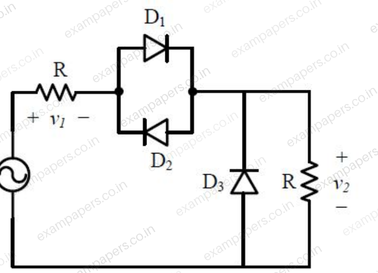
The DC components of voltages
and
, respectively areYour answerChoose one option.
Log in to check the answer
You can attempt this question now. Sign in to view the answer key, explanations and discussion.Log in to check answerQuestion 14
Open questionEE-2MCQ1 markNeeds review
A 3-phase, 4-pole, 400 V, 50 Hz squirrel-cage induction motor is operating at a slip of 0.02. The speed of the rotor flux in mechanical rad/sec, sensed by a stationary observer, is closest to
Your answerChoose one option.
Log in to check the answer
You can attempt this question now. Sign in to view the answer key, explanations and discussion.Log in to check answerQuestion 15
Open questionEEMCQ1 markNeeds review
For the power semiconductor devices IGBT, MOSFET, Diode and Thyristor, which one of the following statements is TRUE?
Your answerChoose one option.
Log in to check the answer
You can attempt this question now. Sign in to view the answer key, explanations and discussion.Log in to check answerQuestion 15
Open questionEE-2MCQ1 markNeeds review
The figure shows the per-phase representation of a phase-shifting transformer connected between buses 1 and 2, where
is a complex number with non-zero real and imaginary parts. 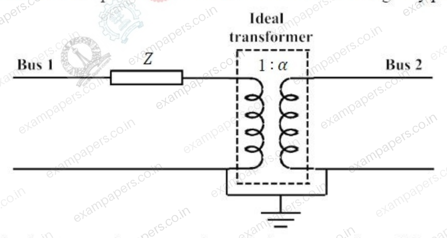
For the given circuit,
and
are bus admittance matrix and bus impedance matrix, respectively, each of size
. Which one of the following statements is true?Your answerChoose one option.
Log in to check the answer
You can attempt this question now. Sign in to view the answer key, explanations and discussion.Log in to check answerQuestion 16
Open questionEENAT1 markNeeds review
Consider
where
. Here,
represents the largest integer less than or equal to
and
denotes the smallest integer greater than or equal to
. The coefficient of the second harmonic component of the Fourier series representing
is ________.Log in to check the answer
You can attempt this question now. Sign in to view the answer key, explanations and discussion.Log in to check answerQuestion 16
Open questionEE-2NAT1 markNeeds review
The figure below shows the circuit diagram of a controlled rectifier supplied from a 230 V, 50 Hz, 1-phase voltage source and a 10:1 ideal transformer. Assume that all devices are ideal. The firing angles of the thyristors
and
are 90° and 270°, respectively. 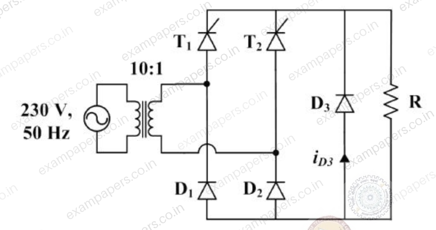
The RMS value of the current through diode
in amperes is _________.Log in to check the answer
You can attempt this question now. Sign in to view the answer key, explanations and discussion.Log in to check answerQuestion 17
Open questionEENAT1 markNeeds review
Let
, where
is the region shown in the figure and
. The value of
equals ________. (Give the answer up to two decimal places.) 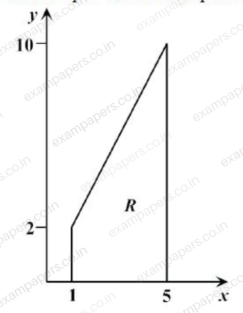
Log in to check the answer
You can attempt this question now. Sign in to view the answer key, explanations and discussion.Log in to check answerQuestion 17
Open questionEE-2NAT1 markNeeds review
Assume that in a traffic junction, the cycle of the traffic signal lights is 2 minutes of green (vehicle does not stop) and 3 minutes of red (vehicle stops). Consider that the arrival time of vehicles at the junction is uniformly distributed over 5 minute cycle. The expected waiting time (in minutes) for the vehicle at the junction is _________.
Log in to check the answer
You can attempt this question now. Sign in to view the answer key, explanations and discussion.Log in to check answerQuestion 18
Open questionEENAT1 markNeeds review
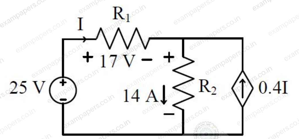
The power supplied by the 25 V source in the figure shown below is ________ W.
Log in to check the answer
You can attempt this question now. Sign in to view the answer key, explanations and discussion.Log in to check answer