
Electrical Engineering
GATE EE topic:power-electronics PYQs
Build your understanding with focused practice from past exam papers.
Questions 31–40 of 66. Imported answers require independent review unless marked reviewed.
Question 61
Open questionEENAT2 marksNeeds review
The steady state current flowing through the inductor of a DC-DC buck boost converter is given in the figure below. If the peak-to-peak ripple in the output voltage of the converter is 1 V, then the value of the output capacitor, in μF, is ________________. (round off to nearest integer)

Log in to check the answer
You can attempt this question now. Sign in to view the answer key, explanations and discussion.Log in to check answerQuestion 24
Open questionEENAT1 markNeeds review
In the circuit shown, the input
is a sinusoidal AC voltage having an RMS value of
. The worst-case peak-inverse voltage seen across any diode is _____ V. (Round off to 2 decimal places.)
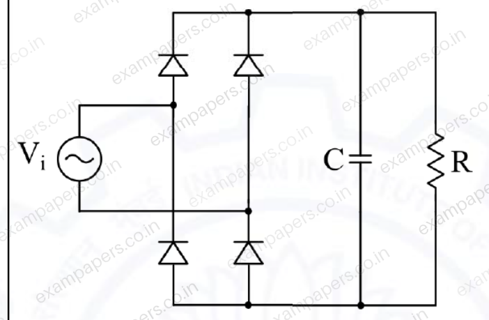
Log in to check the answer
You can attempt this question now. Sign in to view the answer key, explanations and discussion.Log in to check answerQuestion 25
Open questionEENAT1 markNeeds review
In the circuit shown, a 5 V Zener diode is used to regulate the voltage across load
. The input is an unregulated DC voltage with a minimum value of 6 V and a maximum value of 8 V. The value of
is 6
. The Zener diode has a maximum rated power dissipation of 2.5 W. Assuming the Zener diode to be ideal, the minimum value of
is _____
.

Log in to check the answer
You can attempt this question now. Sign in to view the answer key, explanations and discussion.Log in to check answerQuestion 53
Open questionEENAT2 marksNeeds review
Consider the boost converter shown. Switch Q is operating at 25 kHz with a duty cycle of 0.6. Assume the diode and switch to be ideal. Under steady-state condition, the average resistance
as seen by the source is ________
.
(Round off to 2 decimal places.) 
Log in to check the answer
You can attempt this question now. Sign in to view the answer key, explanations and discussion.Log in to check answerQuestion 54
Open questionEENAT2 marksNeeds review
Consider the buck-boost converter shown. Switch Q is operating at 25 kHz and 0.75 duty-cycle. Assume diode and switch to be ideal. Under steady-state condition, the average current flowing through the inductor is ________ A.
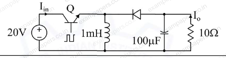
Log in to check the answer
You can attempt this question now. Sign in to view the answer key, explanations and discussion.Log in to check answerQuestion 55
Open questionEENAT2 marksNeeds review
A single-phase full-bridge inverter fed by a 325 V DC produces a symmetric quasi-square waveform across ‘ab’ as shown. To achieve a modulation index of 0.8, the angle
expressed in degrees should be ________.
(Round off to 2 decimal places.)
(Modulation index is defined as the ratio of the peak of the fundamental component of
to the applied DC value.) 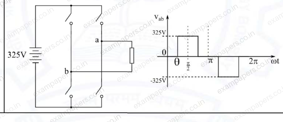
Log in to check the answer
You can attempt this question now. Sign in to view the answer key, explanations and discussion.Log in to check answerQuestion 11
Open questionEEMCQ1 markNeeds review
A single-phase, full-bridge diode rectifier fed from a 230 V, 50 Hz sinusoidal source supplies a series combination of finite resistance, R, and a very large inductance, L. The two most dominant frequency components in the source current are:
Your answerChoose one option.
Log in to check the answer
You can attempt this question now. Sign in to view the answer key, explanations and discussion.Log in to check answerQuestion 12
Open questionEEMCQ1 markNeeds review
Thyristor
is triggered at an angle
(in degree), and
at angle
, in each cycle of the sinusoidal input voltage. Assume both thyristors to be ideal. To control the load power over the range 0 to 2 kW, the minimum range of variation in
is: 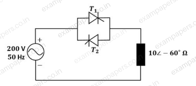
Your answerChoose one option.
Log in to check the answer
You can attempt this question now. Sign in to view the answer key, explanations and discussion.Log in to check answerQuestion 20
Open questionEENAT1 markNeeds review
A double pulse measurement for an inductively loaded circuit controlled by the IGBT switch is carried out to evaluate the reverse recovery characteristics of the diode, D, represented approximate as a piecewise linear plot of current vs time at diode turn-off.
is a parasitic inductance due to the wiring of the circuit, and is in series with the diode. The point on the plot (indicate your choice by entering 1, 2, 3 or 4) at which the IGBT experiences the highest current stress is ____________. 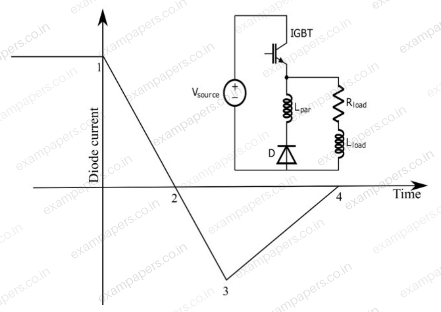
Log in to check the answer
You can attempt this question now. Sign in to view the answer key, explanations and discussion.Log in to check answerQuestion 22
Open questionEENAT1 markNeeds review
A single-phase inverter is fed from a 100 V dc source and is controlled using a quasi-square wave modulation scheme to produce an output waveform,
, as shown. The angle
is adjusted to entirely eliminate the 3rd harmonic component from the output voltage. Under this condition, for
, the magnitude of the 5th harmonic component as a percentage of the magnitude of the fundamental component is ________ (rounded off to 2 decimal places). 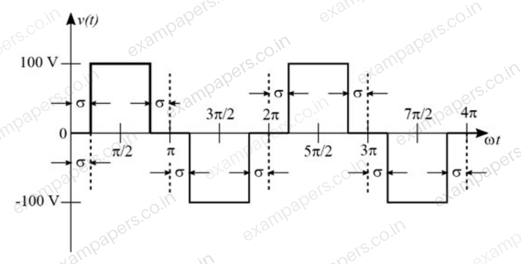
Log in to check the answer
You can attempt this question now. Sign in to view the answer key, explanations and discussion.Log in to check answer