
Electrical Engineering
GATE EE topic:power-electronics PYQs
Build your understanding with focused practice from past exam papers.
Questions 51–60 of 66. Imported answers require independent review unless marked reviewed.
Question 23
Open questionEENAT1 markNeeds review
The waveform of the current drawn by a semi-converter from a sinusoidal AC voltage source is shown in the figure. If
A, the rms value of fundamental component of the current is __________ A (up to 2 decimal places). 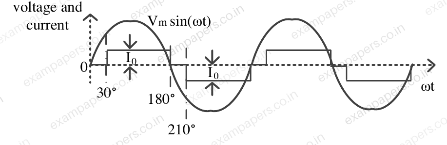
Log in to check the answer
You can attempt this question now. Sign in to view the answer key, explanations and discussion.Log in to check answerQuestion 49
Open questionEENAT2 marksNeeds review
A phase controlled single phase rectifier, supplied by an AC source, feeds power to an R-L-E load as shown in the figure. The rectifier output voltage has an average value given by
, where
volts and
is the firing angle. If the power delivered to the lossless battery is 1600 W,
in degree is_______ (up to 2 decimal places). 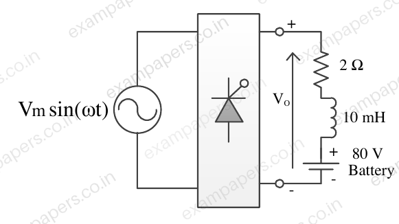
Log in to check the answer
You can attempt this question now. Sign in to view the answer key, explanations and discussion.Log in to check answerQuestion 50
Open questionEENAT2 marksNeeds review
The figure shows two buck converters connected in parallel. The common input dc voltage for the converters has a value of 100 V. The converters have inductors of identical value. The load resistance is 1
. The capacitor voltage has negligible ripple. Both converters operate in the continuous conduction mode. The switching frequency is 1 kHz, and the switch control signals are as shown. The circuit operates in the steady state. Assuming that the converters share the load equally, the average value of
, the current of switch S1 (in Ampere), is ____ (up to 2 decimal places). 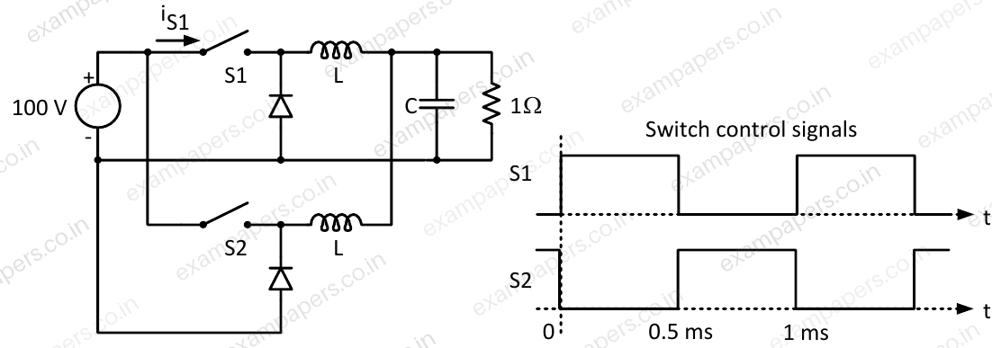
Log in to check the answer
You can attempt this question now. Sign in to view the answer key, explanations and discussion.Log in to check answerQuestion 53
Open questionEENAT2 marksNeeds review
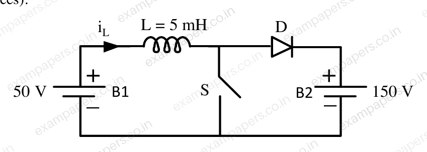
A dc to dc converter shown in the figure is charge a battery bank, B2 whose voltage is constant at 150 V. B1 is another battery bank whose voltage is constant at 50 V. The value of the inductor, L is 5 mH and the ideal switch, S is operated with a switching frequency of 5 kHz with a duty ratio of 0.4. Once the circuit has attained steady state and assuming the diode D to be ideal, the power transferred from B1 to B2 (in Watt) is __________ (up to 2 decimal places).
Log in to check the answer
You can attempt this question now. Sign in to view the answer key, explanations and discussion.Log in to check answerQuestion 11
Open questionEE-2MCQ1 markNeeds review
A phase-controlled, single-phase, full-bridge converter is supplying a highly inductive DC load. The converter is fed from a 230 V, 50 Hz, AC source. The fundamental frequency in Hz of the voltage ripple on the DC side is
Your answerChoose one option.
Log in to check the answer
You can attempt this question now. Sign in to view the answer key, explanations and discussion.Log in to check answerQuestion 12
Open questionEE-2MCQ1 markNeeds review
In the circuit shown, the diodes are ideal, the inductance is small, and
. Which one of the following statements is true? 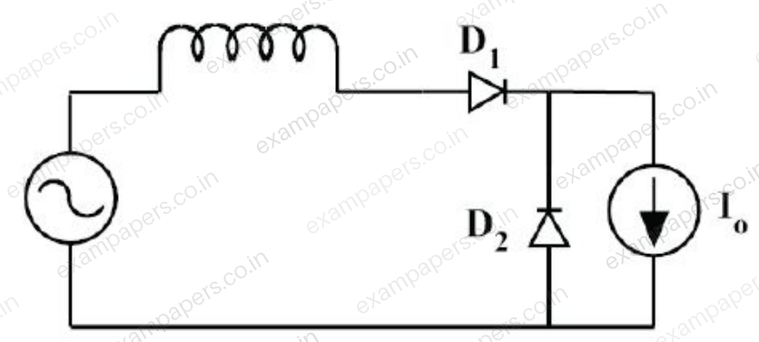
Your answerChoose one option.
Log in to check the answer
You can attempt this question now. Sign in to view the answer key, explanations and discussion.Log in to check answerQuestion 13
Open questionEE-2MCQ1 markNeeds review
A three-phase voltage source inverter with ideal devices operating in 180° conduction mode is feeding a balanced star-connected resistive load. The DC voltage input is
. The peak of the fundamental component of the phase voltage isYour answerChoose one option.
Log in to check the answer
You can attempt this question now. Sign in to view the answer key, explanations and discussion.Log in to check answerQuestion 15
Open questionEEMCQ1 markNeeds review
For the power semiconductor devices IGBT, MOSFET, Diode and Thyristor, which one of the following statements is TRUE?
Your answerChoose one option.
Log in to check the answer
You can attempt this question now. Sign in to view the answer key, explanations and discussion.Log in to check answerQuestion 16
Open questionEE-2NAT1 markNeeds review
The figure below shows the circuit diagram of a controlled rectifier supplied from a 230 V, 50 Hz, 1-phase voltage source and a 10:1 ideal transformer. Assume that all devices are ideal. The firing angles of the thyristors
and
are 90° and 270°, respectively. 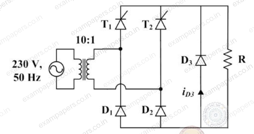
The RMS value of the current through diode
in amperes is _________.Log in to check the answer
You can attempt this question now. Sign in to view the answer key, explanations and discussion.Log in to check answerQuestion 24
Open questionEENAT1 markNeeds review
In the converter circuit shown below, the switches are controlled such that the load voltage
is a 400 Hz square wave.
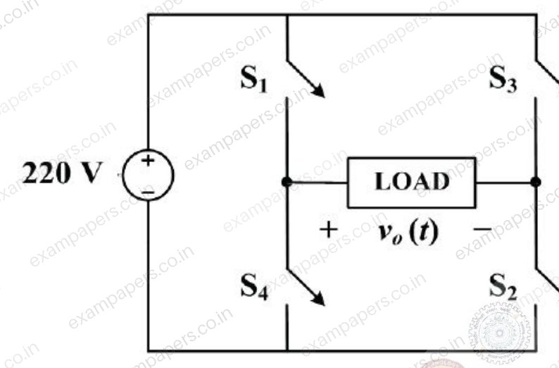
The RMS value of the fundamental component of
in volts is ________.Log in to check the answer
You can attempt this question now. Sign in to view the answer key, explanations and discussion.Log in to check answer