
GATE IN · 2024 · IN
Question 42: Digital Electronics
Give it a try, then reveal the answer to check your work.
Question 42
INMCQ2 marksNeeds review
In the figure shown, the positive edge triggered D flip-flops are initially reset to Q = 0. The logic gates and the multiplexers have no propagation delay. After reset, a train of clock pulses (CLK) are applied. The logic states of the inputs DIN, S and the clock pulses are also shown in the figure. Assuming no timing violations, the sequence of output Y from the 3rd clock to the 5th clock,
is 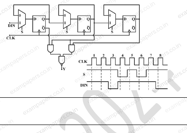
Your answerChoose one option.
Log in to check the answer
You can attempt this question now. Sign in to view the answer key, explanations and discussion.Log in to check answerEXPLORE & PRACTISE
Paper and topic context
See where this question comes from and choose what to practise next.
2024IN
GATE IN 2024 · Paper 1
Instrumentation Engineering · Original paper archive
- Section
- Instrumentation Engineering
- Question type
- Multiple choice (MCQ)
- Marks
- 2 marks
Practise related topics
Explore more previous year questions using this question’s imported topic tags.
instrumentation
GATE IN previous year questions
measurement
GATE IN previous year questions
process control
GATE IN previous year questions
digital electronics
GATE IN previous year questions
Comments
Ask a question, share your approach, or help someone understand.
Log in to view the discussion
You’re not logged in. Log in or create an account to see discussions and add comments.